|
Shaft
Output
|
|
1 = 2m cable
3 = 10m cable



Class I, Zone 1; Zone 21; Class II, Div 2
|
hohner |
Hohner Automation Ltd. |
| Home | About Us | Products | Barriers | Distributors | Custom | News |
|
VIB-00X Explosion Proof Tri-Axial Vibration Sensor (Spider) |
|
|
M | X | K | V | - | 3 | 6 | X | X | - | 0 | 0 | 0 | 0 | |||||||||||
|
| |
Shaft |
Output |
| |
| |
|||||||||||||||||||||
| | | | |
| |
| | T = Triaxial | |||||||||||||||||||||
| | | | | 36 = 4...20mA | | | ||||||||||||||||||||||
| | | | |
|
| | ||||||||||||||||||||||
| | | Shaft Size | Connection | |||||||||||||||||||||||
| | | KV = Vibration |
1 = 2m cable |
|||||||||||||||||||||||
| | |
3 = 10m cable |
||||||||||||||||||||||||
| Protection | |||||||||||||||||||||||||
| E = IP66/67 St. St. | |||||||||||||||||||||||||
| w/ 4x M5 on 2.92" | |||||||||||||||||||||||||
| H = IP66/67 St. St. | |||||||||||||||||||||||||
| w/ 4x 1/4-20 on 2.75" | |||||||||||||||||||||||||
|
Class I, Zone 1; Zone 21; Class II, Div 2 |
|||||||||||||||||||||||||
| Technical Data | Connection Details | ||||||||||||||||||||||||||||
| Operating temp: | - 40 ...+ 60 deg C | Cable | |||||||||||||||||||||||||||
| - 40 ...+ 140 deg F | Ground (0V) | Black | |||||||||||||||||||||||||||
| Vibration: | 5g (500 Hz) | Excitation (+18-36V) | Red | ||||||||||||||||||||||||||
| Shock: | 10g (6msec) | Vib 'a' | Green | ||||||||||||||||||||||||||
| Power supply: | Variable | Vib 'b' | Purple | ||||||||||||||||||||||||||
| Weight: | 2.5Kg | Vib 'c' | Brown | ||||||||||||||||||||||||||
| Protection: | IP 66/67 | ||||||||||||||||||||||||||||
| Housing: | Stainless Steel | ||||||||||||||||||||||||||||
| Humidity: | Up to 98% | ||||||||||||||||||||||||||||
| Vibration Details | |||||||||||||||||||||||||||||
| Sensitivity: | 0.8mA / g (16mA over ±10g) | ||||||||||||||||||||||||||||
| Frequency Resp: | 0 to 1.5 kHz | ||||||||||||||||||||||||||||
| Measuring Range: | ±10g (3 axes) | ||||||||||||||||||||||||||||
| Output Current: | 4...20mA (per axis) | ||||||||||||||||||||||||||||
| Supply Current: | 60 - 120mA | ||||||||||||||||||||||||||||
| Output Setting | <=30ms | ||||||||||||||||||||||||||||
| Outputs | |||||||||||||||||||||||||||||
| 4...20mA: |
-10g = 4mA, 0g = 12mA, +10g = 20mA (each axis, independent output) |
||||||||||||||||||||||||||||
 |
|||||||||||||||||||||||||||||
| Inter-Axis Phase Matching | |||||||||||||||||||||||||||||
|
|||||||||||||||||||||||||||||
| Certifications |
| Does not require a barrier for use in hazardous areas, it is Flameproof, making the barrier redundant. |
| IP 66/X7 |
| Ex d IIC |
| ATEX [Certificate] |
| IECEx [Certificate] |
| CSA [Certificate] |
| GOST-CU [Certificate] |
|
Mounting Instructions |
|
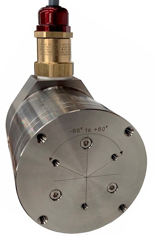
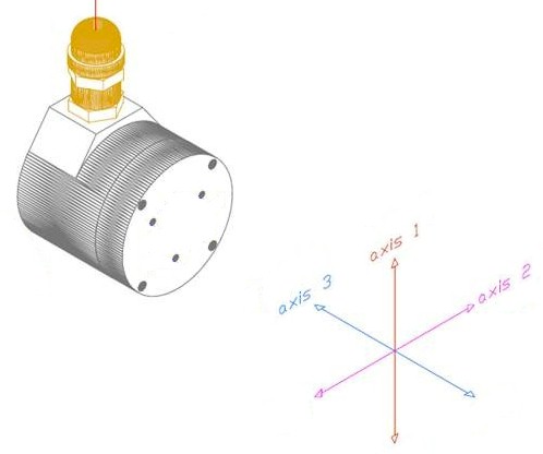
Hook up the vibration sensoer with the connections as described. Make sure power supply meets specifications. Attach unit to machine or device and use the arrows indicating inclination as reference as to which axis the measurements take place.
|
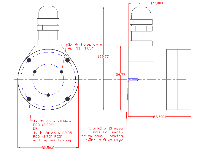
| Dimensions |
|
|
| Hohner Corp. | Tel: 1 905 563 4924 and 1 800 295 5693 |
| 5536 Regional Road 81 | Fax: 1 905 563 7209 |
| Beamsville, Ontario, L0R 1B3, Canada | E-mail: hohner@hohner.com |
| Hohner Automation Ltd. | Tel: +44 (0) 1978 363-888 and 0 845 658 2020 |
| Units 14-16, Whitegate Industrial Estate | Fax: +44 (0) 1978 364-586 |
| Wrexham, North Wales, LL13 8UG, UK | E-mail: uksales@hohner.com |